 Click to enlarge Click to enlarge
|
Description
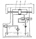
Pump 1 delivers fluid at constant pressure, regulated by relief valve 2, to the left end of cylinder 3, and piston 4, together with machine tool table 5, travels to the right. Fluid exhausted from the right end of cylinder 3 passes through pressure reducing valve 6 and flow-control valve 7. Reducing valve 6 maintains constant fluid pressure before flow- control valve 7. Flow-control valve 7 regulates the pressure in the right end of cylinder 3 so that piston 4 and table 5 travel at the required speed. When flow-control valve 7 is closed to some extent, table 5 and piston 4 travel at lower speed. At this, a part of the fluid delivered by pump 1 is drained through relief valve 2 back to the tank. As valve 7 is opened, table 5 and piston 4 travel at a higher speed.
$4143$CHP,Dr$
|


