 Click to enlarge Click to enlarge
|
Description
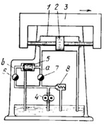
Gear pump 4 delivers fluid at constant pressure to the left end of cylinder 1, and piston 2, together with machine tool table 3, travels to the right. If flow-control valve 7 of pipeline a is fully open and flow-control valve 6 of pipeline b is closed, the total output of pump 4 is delivered to cylinder 1 and table 3 travels at maximum speed. If valve 7 is closed and valve 6 is open, valve spool 5 is shifted to the right, the whole output of pump 4 is discharged to the tank and table 3 stops. Thus, by adjusting flow-control valves 6 and 7, it is possible to regulate the amount of fluid delivered to cylinder 1 and, consequently, the speed of travel of table 3. Surplus fluid is discharged back to the tank through relief valve 8.
$4145$CHP,Dr$
|


