 Click to enlarge Click to enlarge
|
Description
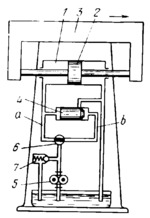
Gear pump 5 delivers fluid at constant pressure through rotary valve 6 to the left end of cylinder 1, and piston 2, together with machine tool table 3, travels to the right. If valve 6 is positioned so that pipeline a is open and pipeline b is closed, table 3 travels at maximum speed, valve spool 4 is shifted to the right by the pressure of the fluid, and the fluid exhausted from the right end of cylinder 1 drains back to the tank. If valve 6 is positioned so that pipeline a is closed and pipeline b is open, the fluid delivered by the pump shifts valve spool 4 to the left and is discharged to the tank. At this, table 3 stops. Thus, by changing the position of valve 6, it is possible to regulate the amount of fluid delivered to cylinder 1 and, consequently, the speed of travel of table 3. Surplus fluid is discharged from the system back to the tank by relief valve 7.
$4146$CHP,Dr$
|


