 Click to enlarge Click to enlarge
|
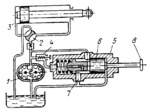
Description
As shown, pump 1 is being unloaded and fluid from the pump passes through automatic valve 5 and port 7 to the tank. During the working operation, spool 6 should be shifted to the left by pushing button 8 and held by a latch (not shown). Fluid is delivered by pump 1 through rotary directional valve 2 to one or the other end of cylinder 3, depending upon the position of valve 2. When the pressure in the system increases during the working operation, a part of the fluid is discharged through valve 4 and port 7 to the tank. At the end of the workinghe stroke, the pressure increases to the extent that it overcomes the resistance of the spring of valve 4 and the latch, so that spool 6 is shifted to the right as shown.
$4164$CHP,Dr$
|


