 Click to enlarge Click to enlarge
|
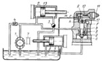
Description
Pump 1 delivers fluid to the left end of cylinder 2 and piston 13 moves to the right. From the right end of cylinder 2 fluid is discharged through flow-control valve 3 to the tank. The pressure developed in the head (left) end of cylinder 2 depends upon the setting of relief valve 4. The pressure in the head (right) end of cylinder 5, used for clamping the stock, should be lower than in cylinder 2. The pressure in the head end of cylinder 5 is regulated as follows. Fluid from the delivery line enters chamber a of the pressure reducing valve through slit d formed by valve member 8 and its seat. From chamber a fluid is delivered to the right end of cylinder 5. Chamber a is connected by passages b and f to chamber k above valve member 8, from where fluid passes through passage e under ball 9, held on its seat by spring 10. The pressure is the same in chambers a and k. Fluid from the system is admitted into cylinder 5, moving piston 6 over to stop 7. After piston 6 reaches the stop, fluid pressure in the right end of cylinder 5 and, consequently, in chamber a increases until ball 9 is pushed off its seat. At this, fluid is discharged to the tank through pipeline m. Since the fluid passes through a passage of small diameter, the pressure becomes higher in chamber a than in chamber k. As a result, valve member 8 moves upward, reducing the cross section of opening d until the pressure in chamber a counterbalances the pressure in chamber k and the force of spring 12. Opening (slit) d automatically maintains a definite pressure. If the pressure in chamber a drops, spring 12 shifts valve member 8 downward, increasing opening d an the admission of fluid to chamber a. This increases the pressure in this chamber until equilibrium is established. Thus, in chamber a, as in the right end of cylinder 5, the required pressure can be set up by adjusting. spring 10 by means of regulating screw 11.
$4183$CHP,Dr$
|


