 Click to enlarge Click to enlarge
|
Description
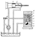
Pump 1 delivers fluid to the left end of power cylinder 2, moving piston 3 to the right. Relief valve 8 maintains constant pressure in the system. A part of the fluid is delivered into chamber a of the reducing valve and from there, through opening d, formed between valve member 4 and the hole of bushing 7, into chamber b with reduced pressure. From there the fluid passes through flow-control valve 5 to the tank. The action of spring 6 on the valve member is counterbalanced by the pressure in chamber b. If the pressure increases in the left end of cylinder 2, the reduced pressure also increases and valve member 4 moves upward, reducing opening d. This reduces the flow of fluid to chamber b and, consequently, the pressure in the chamber. When the pressure drops in the left end of cylinder 2, valve member 4 moves downward, increasing the flow to chamber b and, consequently, the reduced pressure. Thus, constant pressure is maintained before flow-control valve 5, providing for constant speed of piston 3 at each setting of valve 5. This arrangement, consisting of a pressure reducing valve and a flow- control valve, serves as a speed regulator.
$4185$CHP,Dr$
|


