 Click to enlarge Click to enlarge
|
Description
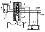
Fluid under pressure is delivered to the right end of cylinder 1 and to valve spool 2. Piston 3 with template 4 is moved to the left by the fluid. Fluid from the left end of cylinder 1 is discharged through a groove of valve spool 2 to the tank. During template travel, stylus 5, held against template 4 by spring 6, raises valve spool 2, admitting fluid to the lower end of fixed cylinder 7, which moves piston 8 and sleeve 9, attached to the piston, upward together with the single-point cutting tool (not shown) until spool 2 blocks off the port of the sleeve. This stops the flow of fluid to cylinder 7. Fluid from the upper end of cylinder 7 is discharged through the valve to the tank. When stylus 5 is moved downward by spring 6 in following the profile of the template, piston 8 and the cutting tool also move downward. Thus the tool motion follows a curve which traces the profile of the template.
$4207$CHP,Dr$
|


