 Click to enlarge Click to enlarge
|
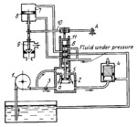
Description
Regulator pump 1, mounted on the turbine shaft, delivers a part of the hydraulic fluid to the upper end of cylinder 2, from where it flows down through drain ports a, and part through flow-control valve 3 to the lower end of cylinder 2. Then the fluid passes through pressure-reducing valve 4, which maintains a constant pressure in the lower end of cylinder 2. Floating piston 5, attached to valve spool 6, is in equilibrium due to the difference in pressure on the two sides of the piston. Upon an increase in turbine shaft speed, the pressure above piston 5 increases due to the increased fluid delivery of pump 1. Piston 5 and valve spool 6 move downward. This increases the clear opening of drain ports a, and equilibrium of piston 5 is restored. As valve spool 6 is shifted downward, fluid delivered to the valve body is directed to the upper end of servomotor 7, moving piston 8 and valve member 9 downward. This reduces the amount of steam supplied to the turbine, as well as the shaft speed. Piston 8 continues to move downward until feedback lever 10, turning about fixed axis A, shifts sleeve 11 of the valve to its central position with respect to valve spool 6. Upon a drop in shaft speed, the elements of the regulator operate in the reverse direction. Turbine shaft speed can be varied by regulating flow-control valve 3.
$4238$CHP,Rg$
|


