 Click to enlarge Click to enlarge
|
Description
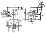
Upon a change in speed of the hydraulic turbine runner, the sleeve of centrifugal governor 1 moves up or down, shifting valve spool 2. Hydraulic fluid from the valve is directed to servomotor 3 and moves piston 4, which changes the position of the guiding device blades. Motion of piston 4 also turns lever 5, shifting cam 6. Roller a rolls along cam 6 and lever 7 shifts valve spool 8. Fluid from the valve is directed to servomotor 9, moving piston 10, which turns the turbine runner blades. Feedback levers 11 and 12, return spool 2 to the central position. Thus, each load or each position of the guiding device blades corresponds to the optimum angle of the runner blades.
$4241$CHP,Rg$
|


