 Click to enlarge Click to enlarge
|
Description
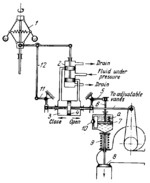
Upon an increase in speed of the hydraulic turbine runner, the sleeve of centrifugal governor 1 moves upward, shifting the spool of valve 2 downward. Hydraulic fluid from valve 2 is directed to servomotor 3, moving piston 4 to the left. This changes the position of the regulating member and the speed is reduced. At the same time, when piston 4 is moving in the closing direction, bell-crank lever 5 and rod 6 move piston 7 of the idle-drain cataract downward. The cataract housing also moves downward, opening idle-drain valve member 8. At this, the required amount of water is drained from the inlet volute chamber to prevent water hammer. Then, spring 9 moves piston 7 of the cataract slowly upward, lifting idle-drain valve 8. At this, fluid slowly flows through flow-control valve 10 from the lower to the upper end of the cataract housing. The velocity of piston return is regulated by means of flow-control valve 10. Feedback levers 11 and 12 return the spool of valve 2 to its central position. When piston 4 moves in the opening direction for the regulating member, upon a reduction in turbine runner speed, idle-drain valve 8 remains closed. This is accomplished by the provision of check valve a in cataract piston 7.
$4242$CHP,Rg$
|


