 Click to enlarge Click to enlarge
|
Description
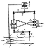
Upon an increase in the amount of air drawn in through pipe a, its velocity also increases as, consequently, does the degree of vacuum at cross section I-I of venturi 1 and in the upper end of cylinder 8. Atmospheric pressure moves piston 2 upward, shiftinhg valve spool 3 in the same direction. Hydraulic fluid from the valve is delivered to the lower end of servomotor 4, moving its piston upward. This turns lever 5 about fixed axis A and lowers shutter 6, reducing the amount of air drawn in. As shutter 6 is moving downward, lever 7 turns about axis D and shifts valve spool 3 downward, stopping fluid delivery to the servomotor. Upon a decrease in the amount of air drawn in through pipe a, the pressure at cross section I-I increases, piston 2 is moved downward by spring 8 and the elements of the regulator operate in the reverse direction.
$4258$CHP,Rg$
|


