 Click to enlarge Click to enlarge
|
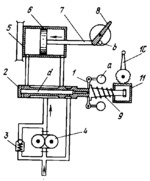
Description
Upon an increase in engine speed, balls a of centrifugal governor 1 move outward, shifting valve spool 2 to the right. At this, pump 4 delivers hydraulic fluid through the valve to the right end of cylinder 5, moving piston 6 to the left. Pin b, mounted on piston rod 7, turns propeller blade 8 clockwise, increasing the propeller pitch and, consequently, reducing the engine speed to the preset value. Fluid from the left end of cylinder 5 is discharged through axial passage d in spool 2 to the suction line of pump 4. Relief valve 3 protects the system against overloads. Upon a reduction in engine speed, balls a move inward, valve spool 2 is shifted to the left by spring 9, fluid from the pump is delivered to the left end of cylinder 5, moving piston 6 to the right. At this, propeller blade 8 is turned counterclockwise by a spring (not shown), reducing the propeller pitch. The regulator can be set up for any required engine speed by turning lever 10 which, through gear rack 11, regulates spring 9.
$4265$CHP,Rg$
|


