 Click pentru a mări Click pentru a mări
|
Description
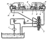
Pump 1 delivers fluid through four-way valve 2 to the right end of working cylinder 3. The pressure of the fluid moves piston 4 and rod 5 to the left, advancing fixture 7, sliding in guides x-x together with clamped work 8, to milling cutter 6. The work is clamped by lever 11, whose shank runs onto roller 12 when fixture 7 is advanced. The left end of cylinder 13 is connected to the tank and piston 14, together with fixture 15, is moved by heavy spring 16 to the initial position to remove the milled workpieces and load new blanks. Check valve 10 prevents the fluid from being discharged during operation. Relief valve 9 maintains the required fluid pressure in the system. In the lower position of the valve spool, the delivery line of pump 1 is connected to the left end of working cylinder 13, performing the milling operation with the left-hand fixture. The right end of cylinder 3 is connected to the tank, retracting the right-hand fixture to remove the milled workpieces and to load new blanks.
$4288$CHP,GC$
|


