 Click to enlarge Click to enlarge
|
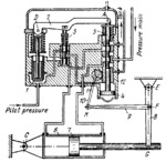
Description
Power cylinder 6 turns about fixed axis C and has piston 7, connected by turning pair G to lever 8, which turns about fixed axis E. Link 9 is connected by turning pairs F and K to lever 8 and to link 10, which is attached to segment gear 11. Gear 11 meshes with a gear rack of sleeve 12. Upon an increase in the pilot pressure at the bottom of plunger 1, the plunger is shifted upward, turning lever 2 about axis A. Lever 2 shifts valve spool 3 upward, delivering fluid to the space above piston 4. This shifts valve spool 5, rigidly attached to the piston, downward. At this, high-pressure fluid, delivered from the main to spool 5, is directed to the right end of power cylinder 6, which controls the flaps of the plane. From the left end of cylinder 6, fluid is discharged through a groove of spool 5 to the tank. As spool 5 is shifted downward, it turns lever 2 about axis D, returning spool 3 to its neutral position. Thus, the system is transferred to a new state of equilibrium, determined by the magnitude of the pilot pressure. As piston 7 moves to the left, motion is transmitted through lever 8, links 9 and 10, and segment gear 11 to sleeve 12. As the sleeve is shifted, it blocks off the connections between the ends of cylinder 6 and the high-pressure main and tank. Upon a decrease in pilot pressure, the elements of the system operate in the reverse direction.
$4306$CHP,FD$
|


