 Pinche para ampliar Pinche para ampliar
|
Description
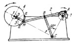
The lengths of the links comply with the conditions: A͞B=C͞B=B͞M=1, E͞A=0.19, C͞E= 1.11, M͞D=0.403, F͞D=0.12 and C͞F=2.05. Point M of connecting rod 2 in four-bar linkage EABC describes connecting-rod curve a-a of which the portion shown by a heavy continuous line approximates a circular arc of radius D͞M with its centre at point D. When point M travels along this portion, link 4, designed as a flywheel, remains almost stationary, i.e. it practically has a dwell. At one of the extreme positions (dead points) of the mechanism (shown in the drawing), points F, D and M lie on a single straight line. From this position, flywheel 4 can begin rotating either clockwise or counterclockwise. Consequently, one revolution of crank 1 corresponds to one revolution of flywheel 4 in the same direction and with a prolonged dwell, or to one revolution in the opposite direction with no dwell.
$756$LW,D$
|


