 Click pentru a mări Click pentru a mări
|
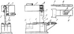
Description
When the press ram with punch-holder 1 descends, hinge 2, pivoted to the punch-holder, moves downward with its rigidly attached cam-arm 3. When the angular edge at the bottom of projection a of cam-arm 3 engages edge d of opening b in slide 4, hinge 2, together with cam-arm 3, is turned about pivot A in the direction of the arrow, depressing spring-actuated plunger 5. At this point, cam-arm 3 is in the position shown by dash lines in opening b, and slide 4 is stationary. As the ram and punch-holder 1 continue to descend, projection a of cam-arm 3 passes the corner at d, so that recess c allows the cam-arm to be swung back to its normal position (corresponding to the section- al area in opening b) by plunger 5. As the press ram and punch- holder 1 begin to ascend, the angular portion at the top of projection a engages the under side at corner d, causing slide 4 to move to the right together with workpiece locating stop 7 to which it is rigidly attached. At this moment, the finished part is ejected from the die and a new blank 8 is fed into place by a special feeding device (not shown). As the press ram continues its upward motion, projection a leaves slide 4 which is returned by spring-actuated plunger 6 to its position for locating blank 8. The action of slide 4 can be timed accurately with respect to the ram stroke by adjusting cam-arm 3 to the required position a long hinge 2.
$3244$CmL,SF$
|


