Structure of mechanism |
| Function |
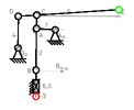
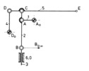
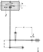
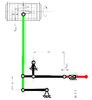
Bild 5.1/12 zeigt das kinematische Schema des Übertragungsgestänges. Die Glieder 1, 2, 3 und 6;0 bilden eine Schubkurbel. An deren Koppelpunkt C ist das Glied 5 angelenkt, das außerdem im Gelenk D durch das im Gestell gelagerte Glied 4 geführt wird.
- Übertragungsgetriebe zur Umwandlung einer Schubbewegung in eine maßstäblich vergrößerte, geradlinige Positionierbewegung des Koppelpunktes
- Ebenes Stephenson-3-Getriebe
Zusätzliche Informationen sind in Getriebetechnik in Beispielen zu finden. |
| Dimension of mechanism |
planar |
| Number of links |
6 |
| Drive movement |
Rectilinear translation |
| Output movement |
Position |
| Degree of freedom |
1 |
| Fundamental mechanism |
 Link containing mechanism Link containing mechanism |
| Number of inputs |
1 |
| Number of followers |
1 |
| Revolution ability |
no |
| Revolution ability of input link |
no |
| Relative position between drive and output |
parallel |
| |
Guidance function |
| Direction of the path |
identical direction |
| Orientation of output link |
general |
| Trace of a dedicated point on follower |
 Open trace Open trace
 Specified trace Specified trace |
| Dimension of mechanism |
planar |
| Input reference |
yes |
| Progress of orientation respecting output link |
revolving |
| |
Transfer function |
| Output motion |
high deviation |
| Transfer function |
 identical direction identical direction |
| |
Application |
| Application area |
Other fields |
| Examples of application |
Registriergerät |
| |


 Animations
 CAX files
 Images
 Start interactive animation