 Click to enlarge Click to enlarge
|
Description
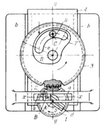
The mechanism is intended for machining cam slots of a shape based on a sine law. Driving gear 1 rotates about axis A of slide 4. Link 5 is connected by turning pair B to slider 2 which moves along fixed guides a-a, and by a turning pair to slide 4 which moves along fixed guides b-b. End milling cutter 6 rotates about fixed axis C. Gear 1 meshes with gear 3 on which cam blank 7 is rigidly clamped. Gear 3 rotates about axis D of slide 4. When driving gear 1 rotates, blank 7 is displaced along axis y-y by a distance equal to y=y₀±r sin(ϕ) and rotates through an angle equal to ψ=(z₁/z₃)ϕ where y₀ is the initial coordinate determining the position of slide 4, r is the distance A͞B, ϕ is the angle between line AB and axis x-x, and z₁ and z₃ are the numbers of teeth of gears 1 and 3. Milling cutter 6 machines slot e in blank 7. Displacement y can be varied by changing length A͞B. This is done by clamping axis B at the required position in slot d.
$2572$LrG,FD$
|


